Today, I’m going to be starting a new series exploring the portable executable format. I’ve been working a lot with the format lately, so I decided to document my journey in a series of articles. The series will begin with a fairly broad overview of the format and then subsequent articles will begin a deeper dive into the more complex topics — like imports, exports, debug data, exception handling, etc.
There are lots of articles out there that cover bits and pieces of what I’m going to be walking you through. But I’m hoping to create something that combines that information in a practical way, not just create a lengthy reference guide. So if you came across this while working on your own hobby compiler or you just want to learn a bit more about how the Windows program loader works, you’ve come to the right place!
Before we jump in, I want to take a quick moment to acknowledge a few of the resources that were helpful to me in preparing this series:
- “Tiny PE”, a fun article describing the quest to create the world’s smallest PE file.
- “Portable Executable”, the Wikipedia entry, which has some very helpful diagrams.
- “PE Format”, a rather long (but very verbose!) description of the format from MSDN.
What Is a PE File?
Before we can answer that question, we need to take a step back and imagine a very simple computer. This simple computer reads instructions (machine code) from a tape reel and executes them. These instructions are continuously read one after the other and executed immediately as they are read from the reel. They do things like send data to a printer, check to see if a keyboard button has been pressed, or calculate which pixels on the display to use for displaying the letter “P”.
The immediately obvious problem with this simple machine is that it lacks the means to jump around to different instructions so let’s instead upgrade our imaginary computer to use a disk drive that can seek forwards and backwards on the disk. Once again, we quickly find another problem — seeking is slow. It takes time for the internals of the drive to reposition themselves. With this in mind, it now becomes obvious that we need a form of storage that allows for very fast random access. That phrase should sound familiar because we have just described random access memory (RAM).
Let’s have our imaginary computer start by reading a block of instructions from the disk into memory (RAM). Instead of reading and executing instructions from a slow disk drive, our computer reads them sequentially from memory, using a special pointer (called a register) to keep track of which instruction is the current one. Problem solved!
It might seem like our imaginary computer is complete but we quickly run into issues when we start using several programs…
The programs for our imaginary computer contain all of the code that they need to run, from start to finish. But, it turns out, there are large blocks of code that are identical in every program. If every program displays text on the screen, then it seems wasteful to have copies of that code in each program. We need a way to share code between programs. Also, not everything that a program requires to run is code. Some programs display images onscreen or play sounds.
We need a way for programs to contain code, data, and information about how to run them.
This is where PE files come in. They are image files. They contain code but also reference code in other programs (imports), provide code to other programs (exports), contain information about how they should be loaded into memory, and embed other data. They are fairly complex, since programs can do a lot of different things in a lot of a different ways. But now that we know what the format is, we can start looking at how it works.
A Quick Note (or Two)
To keep the scope of my article series from getting too big, I’m not going to be covering the process of assembly — that is, producing the raw stream of machine code instructions. There are handy reference materials for this easily available and there’s no point wasting space reprinting it all here. (Not to mention that it’s several hundred pages!)
Also, the examples below will use NASM, the Netwide Assembler. Go ahead and grab a copy of that if you want to follow along. Although you will need a copy of Windows (or something like Wine) to actually run the examples, you can build them on nearly any platform since NASM runs on all of the major ones.
Creating Our First File
Due to the way the many parts of the file reference each other, we can’t just incrementally create our first PE file and have something usable.
Therefore, I will give you the entirety of the “simplest” PE file we can create and then slowly walk you through each of the different parts. Begin by creating a new file simple.asm and entering the contents below:
; Use 32-bit instructions
BITS 32

; File begins at the following address in memory
ImageBase equ 0x400000

dos:
    dw "MZ"         ; Magic number
    times 29 dw 0   ; Empty DOS header

hdr:
    dd filehdr      ; Offset to fileheader

filehdr:
    dd "PE"         ; Signature
    dw 0x014C       ; Machine
    dw 1            ; NumberOfSections
    dd 0            ; TimeDateStamp
    dd 0            ; PointerToSymbolTable
    dd 0            ; NumberOfSymbols
    dw opthdrsize   ; SizeOfOptionalHeader
    dw 0x0103       ; Characteristics

opthdr:
    dw 0x10b        ; Magic
    db 0            ; MajorLinkerVersion
    db 0            ; MinorLinkerVersion
    dd codesize     ; SizeOfCode
    dd 0            ; SizeOfInitializedData
    dd 0            ; SizeOfUninitializedData
    dd start        ; AddressOfEntryPoint
    dd code         ; BaseOfCode
    dd 0            ; BaseOfData
    dd ImageBase    ; ImageBase
    dd 1            ; SectionAlignment
    dd 1            ; FileAlignment
    dw 4            ; MajorOperatingSystemVersion
    dw 0            ; MinorOperatingSystemVersion
    dw 0            ; MajorImageVersion
    dw 0            ; MinorImageVersion
    dw 4            ; MajorSubsystemVersion
    dw 0            ; MinorSubsystemVersion
    dd 0            ; Win32VersionValue
    dd filesize     ; SizeOfImage
    dd hdrsize      ; SizeOfHeaders
    dd 0            ; CheckSum
    dw 2            ; Subsystem
    dw 0            ; DllCharacteristics
    dd 0x100000     ; SizeOfStackReserve
    dd 0x1000       ; SizeOfStackCommit
    dd 0x100000     ; SizeOfHeapReserve
    dd 0x1000       ; SizeOfHeapCommit
    dd 0            ; LoaderFlags
    dd 16           ; NumberOfRvaAndSizes

; Data directories
    times 16 dd 0, 0

opthdrsize equ $ - opthdr

; .text section
    db ".text", 0, 0, 0 ; Name
    dd codesize         ; VirtualSize
    dd code             ; VirtualAddress
    dd codesize         ; SizeOfRawData
    dd code             ; PointerToRawData
    dd 0                ; PointerToRelocations
    dd 0                ; PointerToLinenumbers
    dw 0                ; NumberOfRelocations
    dw 0                ; NumberOfLinenumbers
    dd 0x60000020       ; Characteristics

hdrsize equ $ - hdr

; The code for the program

start:
code:
    mov eax, 42
    ret

codesize equ $ - code

filesize equ $ - $$
Whew! We just used NASM to describe the contents of a (very!) simple PE file. I use the word “describe” here because we have literally provided NASM with a byte-for-byte description of what the file should contain.
To convert the description to an executable, invoke NASM as follows:
nasm -f bin simple.asm -o simple.exe
This should produce a file that is exactly 358 bytes. One of the benefits of creating the file this way is that we can account for every single byte in the file! You can try running the newly-created program but it won’t do much. In fact, all it does is set the exit code (or return code) to 42 and then quit.
Let’s take a closer look at what’s inside.
Getting Started
The first thing we do is use the BITS macro to indicate that any instructions generated for this file should be 32-bit (or more specifically, operate in protected mode). The ImageBase definition is for convenience when we start adding more to our PE file later. For now, it simply indicates the starting address in memory where our image will be loaded.
The “dd”, “dw”, and “db” directives indicate what value the next 4, 2, and single bytes should contain, respectively. For example:
db "TEST"
dw 0xffff
dd 0x400000
…indicates that the file should contain the four bytes that represent the ASCII values for “T”, “E”, “S”, and “T”, followed by the 16-bit unsigned value 0xffff, followed by the 32-bit unsigned integer 0x400000. In this way, we build our PE file byte-by-byte.
The Headers
The first two bytes of a PE file are always the ASCII characters “MZ”. Why these two? They are the initials of Mark Zbikowski, one of the MS-DOS developers.
What follows from there is the DOS header and stub. The PE format was originally designed so that programs could be both valid DOS applications and valid PE files. Our example is only designed to run on Windows, so in our simple example, we write 29 blank words (16-bit unsigned integers). The last four bytes of the DOS header point to the beginning of the PE parts of the file. In NASM, we can use labels to avoid specifying the location by hand.
File Header
The next four bytes consist of the values “PE\0\0”. Following that is the IMAGE_FILE_HEADER, which indicates:
Machine— the CPU architecture that this file is designed to be run on;0x014cindicates x86,0x8664indicates x64, and0xaa64indicates ARM64NumberOfSections— the number of sections in the file (more on this in a bit); our example only has one sectionTimeDateStamp- the time that the file was linked; but it is entirely optional and can be set to0for our examplePointerToSymbolTableandNumberOfSymbols— we will explore the symbol table in a later article; for now, we will leave these both at0SizeOfOptionalHeader— the size, in bytes, of the optional header (the next part of the file, more on this in a bit)Characteristics— information about how certain parts of the file should be treated; we use the following values in our example (combined with bitwise AND):IMAGE_FILE_RELOCS_STRIPPED(0x0001) — the file doesn’t use relocations, meaning we require it to be loaded at the address we specified above (when we definedImageBase)IMAGE_FILE_EXECUTABLE_IMAGE(0x0002) — the file has all of its external references resolved; that is to say it is an EXE, not a DLL, or an OBJ file (though we will learn about those later!)IMAGE_FILE_32BIT_MACHINE(0x0100) - the file is designed to run on a 32-bit system
Optional Header
Following the file header is the IMAGE_OPTIONAL_HEADER32 or the IMAGE_OPTIONAL_HEADER64 (depending on the architecture). In our case we use IMAGE_OPTIONAL_HEADER32:
Magic— another field that needs a specific value; in the case of a 32-bit application,IMAGE_NT_OPTIONAL_HDR32_MAGIC(0x10b)MajorLinkerVersionandMinorLinkerVersion— the major / minor version of the linker used to produce this file; we can leave these at0; we made this file ourselves — no linker needed!SizeOfCode— the size of the section that contains the code (which we will be looking at shortly)SizeOfInitializedDataandSizeOfUninitializedData— we have neither initialized nor uninitialized data in our example, so these can both be set to0AddressOfEntryPoint— this is the address where execution of our program will startBaseOfCode— the address of the section that contains the code (which, in this particular case, is exactly the same as theAddressOfEntryPoint; however, we still use separate labels to avoid confusion when we begin adding to our example in subsequent articles)BaseOfData— the address of the data section; we don’t have one, so this can be set to0ImageBase— the address in memory where the PE file should be loaded; we use theImageBasethat we defined above specifically for this purposeSectionAlignmentandFileAlignment— the alignment value for sections in memory and in the file, respectively; we can avoid the complexity of aligning the sections in our program for now by setting these both to1; it will still run without issueMajorOperatingSystemVersionandMinorOperatingSystemVersion— the minimum operating system version required to run the file; our example will run on any version of Windows all the way back to Windows 4.0 (more commonly known as Windows 95)MajorImageVersionandMinorImageVersion— the version for this image; we can use whatever we want here but we will simply leave them both at0MajorSubsystemVersionandMinorSubsystemVersion— the version of the subsystem required to run the program; we use the same values as we did forMajorOperatingSystemVersionandMinorOperatingSystemVersionWin32VersionValue— reserved and must be set to0SizeOfImage— the size of the file (in bytes)SizeOfHeaders— the size of the headers from thehdrlabel to the end of the section headers (more on these later)CheckSum— the checksum verifies the integrity of the file; it is computed using theMapFileAndCheckSumAandMapFileAndCheckSumWfunctions in the Windows API; it is only verified under certain circumstances, so we can just set it to0Subsystem— the subsystem the program is designed for; this has a lot of esoteric values for special cases, but the two you are probably most familiar with are:IMAGE_SUBSYSTEM_WINDOWS_GUI(0x2) — Win32 GUI applicationIMAGE_SUBSYSTEM_WINDOWS_CUI(0x3) — Win32 console application
DllCharacteristics— special flags for DLL files (which we can ignore since our program isn’t a DLL)SizeOfStackReserve,SizeOfStackCommit,SizeOfHeapReserve, andSizeOfHeapCommit— the number of bytes to reserve and commit for the stack and heap, respectively; we will take a look at the stack and heap later; use the provided values for nowLoaderFlags— obsolete; we leave this at0NumberOfRvaAndSizes— number of directory entries (see next)
Congratulations for making it this far! That was a big wall of text.
Data Directories
There are typically 16 data directories, so NumberOfRvaAndSizes should be set to 16. Immediately following is an array of IMAGE_DATA_DIRECTORYs.
Each directory entry contains two double-words (32-bit unsigned integers), VirtualAddress and Size. We will look much more closely at the data directories when we start discussing imports, but for now, we will simply write out 16 blank entries.
Section Table
The last of the headers is the section table. This table provides the program loader with a list of the different sections in the file. Sections divide the contents of the PE file into different purposes. We only need one section in our example and it will contain code.
Entries in the table are IMAGE_SECTION_HEADER instances:
Name— 8-byte name for the section; code is typically store in a section named “.text” (don’t forget to pad it with\0to fill 8 bytes)VirtualSize— the size of the section in bytes when loaded into memoryVirtualAddress— the address in memory where the section is loadedSizeOfRawData— the size of the section in the PE filePointerToRawData— the offset of the section in the PE filePointerToRelocations,PointerToLinenumbers,NumberOfRelocations, andNumberOfLinenumbers— we don’t use relocations or line numbers in our example, so these are set to0Characteristics— information about how the section should be loaded into memory; our example uses the following flags:IMAGE_SCN_CNT_CODE— section contains codeIMAGE_SCN_MEM_EXECUTE— section is executableIMAGE_SCN_MEM_READ— section is readable
Of particular note in these entries is the distinction between the PE file on disk and how it is laid out in memory. It is possible to have a section defined in the PE file on disk that takes up more space in memory. This is useful for sections that we want initialized to 0 when our program starts — without storing all of those useless 0’s in the file.
The .text Section
Finally, the meat of the application. Our code begins at the entry point and consists of two instructions:
mov eax, 42
ret
These simply set the program’s exit code to 42. We will expand this to something more useful in later articles, but for now, it will do.
Examining PE Files
One more thing before we wrap up the first article. Can we take a look at an existing PE file and see if we recognize anything? We sure can! For that, there are a number of wonderful tools:
- Ghidra — a whole suite of tools for reverse-engineering PE files (requires the JDK)
- Relyze — interactive tool for viewing and visualizing PE files
- WinDbg — the Windows debugger
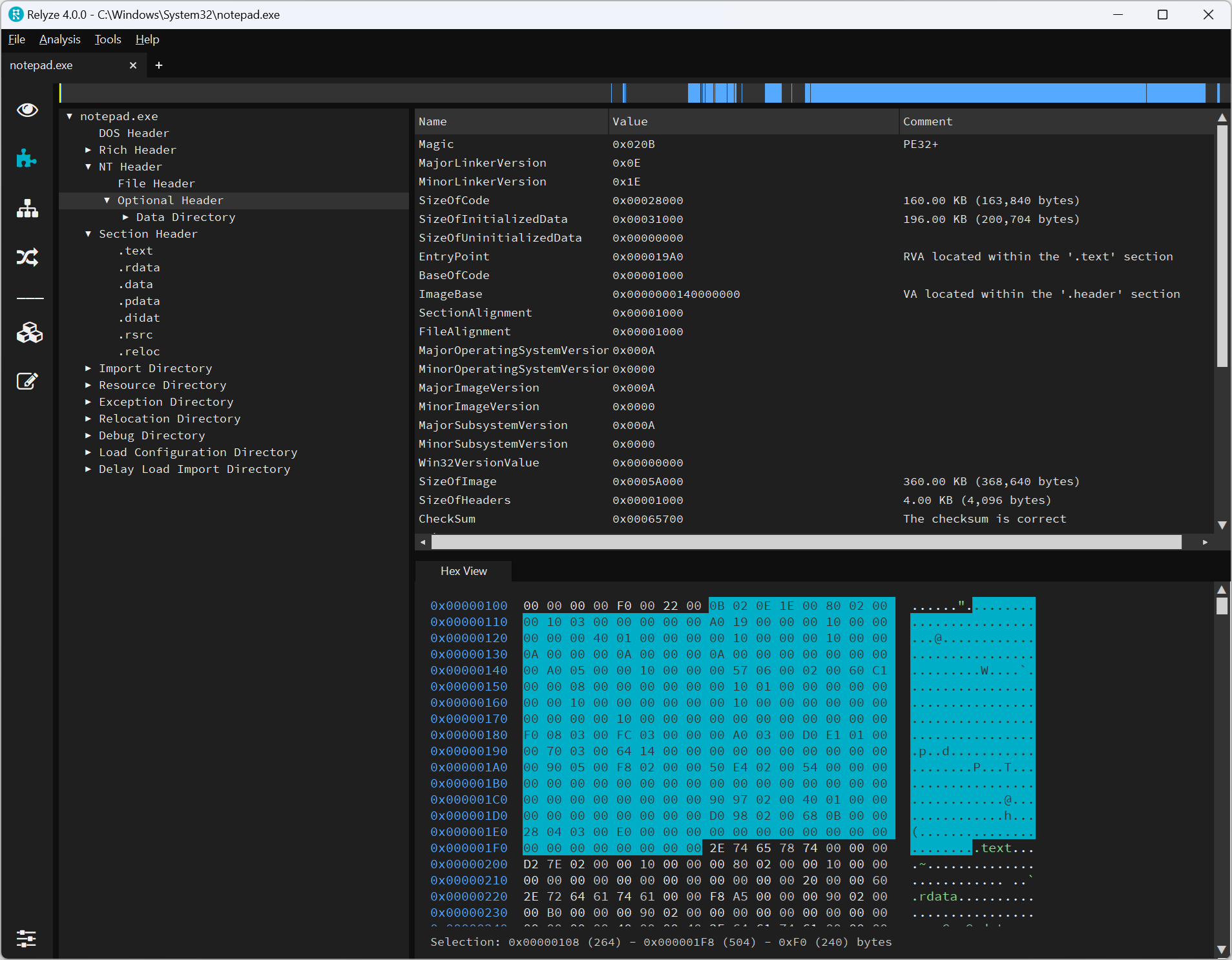
For example, here’s what you get opening Notepad (C:\Windows\System32\notepad.exe) in Relyze and peeking at what’s inside:
WinDbg is handy when you want to see what your PE file looks like once it’s loaded into memory. This will come in handy in Part 2, when we take a look at imports and write a program that actually does something onscreen!